Bricks Overview
The brick is an essential extention to the Base station. It provides connectors for different sensors (not only 1-wire temeprature sensors, such as supported by the the Base station), but also digital and analog inputs. Additionally to this, a sheer limitless amount of bricks (up to 60K) can be connected to a single Base station.
Next to the data capture capabilites, it also provides outputs/actors, which can be controlled via the base station as well as the Direct Rule feature on the brick itself. This permits a realtime control of time critical applications.
Getting started
1. Find a location which is dry and not too hot (operating temperature from -20 to 70 deg. celcius).
The brick is neither water nor splash water proof. Immersing the brick into water will break it and
void any warranty.
2. Mount all sensors to the brick. The brick is not connected to the power supply yet.
Chapter layout and connectors explains how to attach the various sensors.
3. Once all the sensors are connected, the brick can be powered up. Check chapter power connectors for more details.
4. Make sure, that the brick is properly synchronized with the XBee network of the Base station. This can
be checked by observing the association LED on board.
5. Use the network tools (like ping or ND) on the base station to confirn the integration into the
the XBee radio network. The Manual Test Sensor Network
explains in detail how to use this toolset proficiently.
6. Add your brick to the data model. Check chapter
Newly discovered bricks on how to incorporate the new brick to TMOR.
Layout and connectors
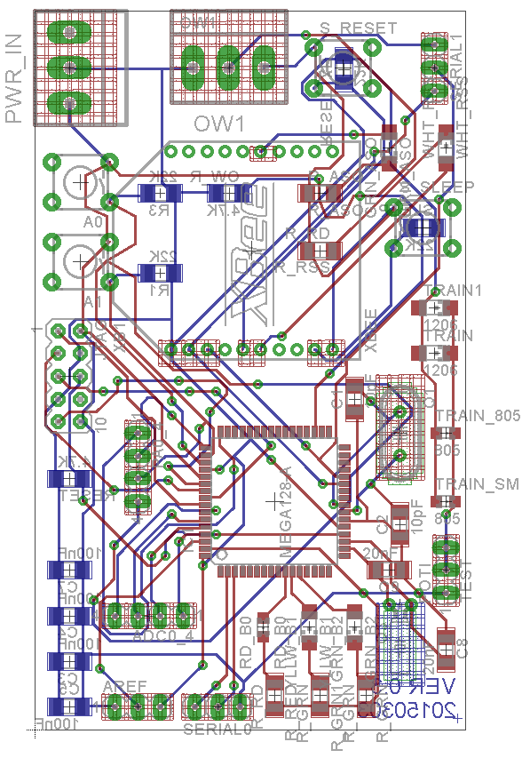
How to check for my version?
With each version, connectors and layout may change. Make sure to double check your version. The version number is marked as Ver. xxx. on the back or front side of the layout. According to the version, the capabilites of the brick might differ. See Feature Matrix for more details.
Layout Version 1.0
Layout Version 2.0
Brick Version 2 comes along with an addon shield. This addon shield provids additional connectors, which are not necessary when operating the brick in minimum mode (e.g. only using 1-wire temeprature measurement).
The below shown layout board is splint into two in the middle. On the left hand side the brick basis board is shown. On the right hand side the addon shield is displayed.
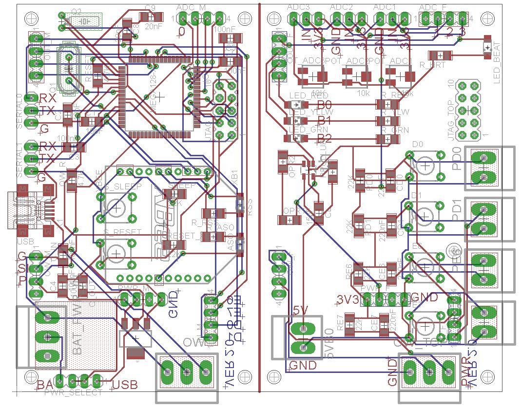
The addon shield is placed on to of the basis board. 5 * 4 pin rows provide connection between the two boards.
Serial connectors Version 2.0
The brick provides the following serial interfaces:
- Serial interface 0: The debug interface and can be neglected for normal operation.
- Serial interface 1: The communication interface. It is connected to the XBee radio module.
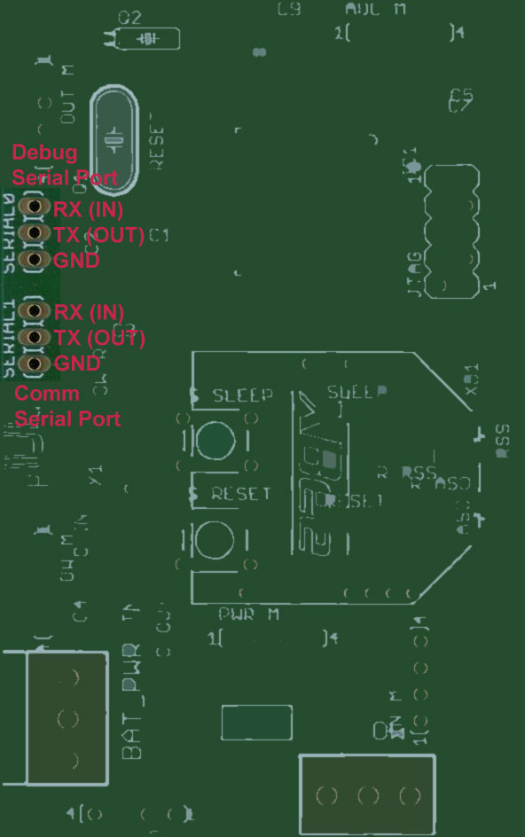
Note: When connecting a terminal to the serial interfaces, make sure to connect the terminal send line (TX) to the brick RX line and the terminal receive line (RX) to the brick TX line. Also connect the ground (GND) line so provide a stable electrical potential. A good practice is to decouple the connected line with some small resistors to protect the electronic parts in case of increased potential difference. The power level of the serial ports is 3.3 volts. Check Timing characteristics for Serial Ports to configure the correct baud rate.
Part of the communication between TMOR Base station an Brick is
documented here.
To track the communication on the physical level, send off a command towards the brick by creating a text file and writing it into the
tobrick folder. Chapter Communication files
describes the process in detail.
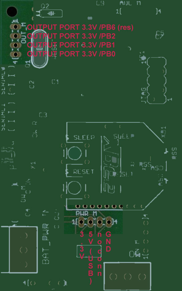
Power connectors Version 2.0
Version 2.0 provides two power modes:
- USB port: Use a Raspberry Pi 3 Power Supply Adapter with the USB micro connector
- Battery pack: Take the 3.0V battery pack with 12 AAA batteries
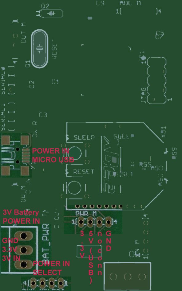
We strongly reccomend to connect only one of the two power sources. Use the jumper on the POWER SELECT Pins in order to specify which power source to drain the current from.
1-wire temperature sensor connector Version 2.0
Version 2.0 provides two power modes:
- USB port: Use a Raspberry Pi 3 Power Supply Adapter with the USB micro connector
- Battery pack: Take the 3.0V battery pack with 12 AAA batteries
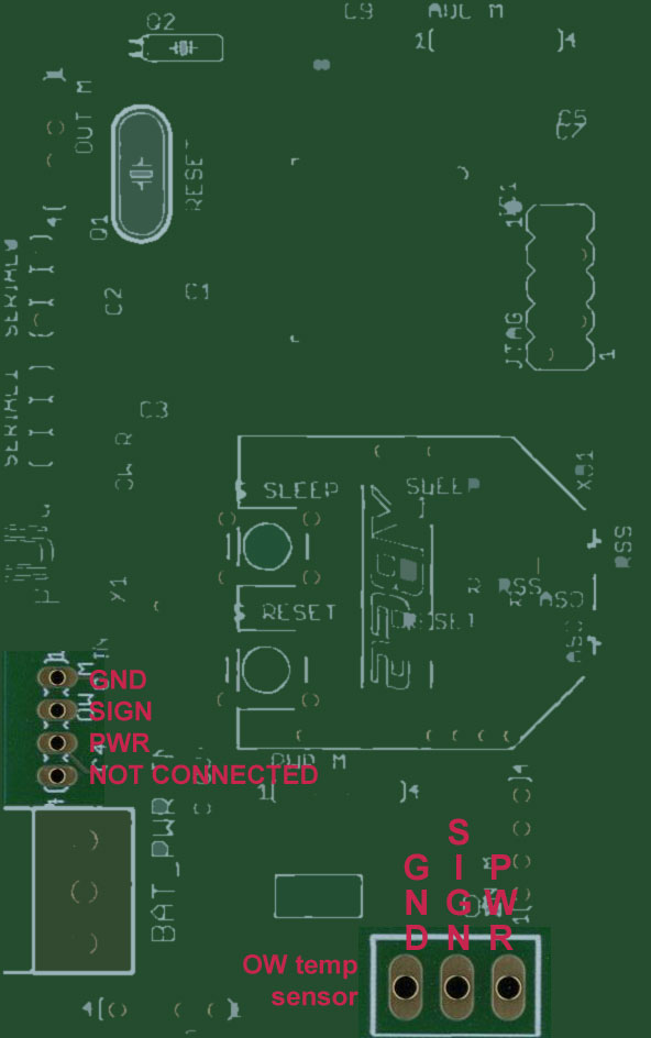
The 1-wire sensor can be connected either at the brick ground platine (as shown above) or on the addon shield. The pin socket on the left provides the break-though to the addon shield.
ADC and digital input connectors V 2.0
Version 2.0 provides the following input ports:
- 1 time 1-wire temperature input port for DS18B20 / polling mode
- 3 times ADC ports with resultion of 2014 bits / polling mode
- 4 times digital IO ports - interrupt driven
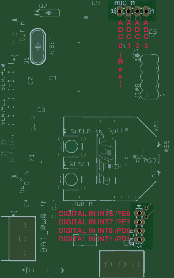
The addon shield provides the skrew clamps to connect your sensors properly. The digital input lines need a low pass filter to debounce the switch. This hardware is provided on the addon shield.
Digital output ports V 2.0
Version 2.0 provides the following output ports:
- 3 low power 3.3V output ports
- the addon shield visualizes the output status via red, yellow and green leds
The addon shield
The addon shield is only available from Version 2.0 onwards.
It provides the following features:
- 3 low power 3.3V output ports (B0, B1, B2)
- 3 low power output ports (B0, B1, B2) are connected to LEDs
- 1 output port powered also @ 5V (B0)*
- 3 ADC input connectors with trimming poentiometers
- 4 debounced digital input ports (D0, D1, E6, E7) with test switches on the board
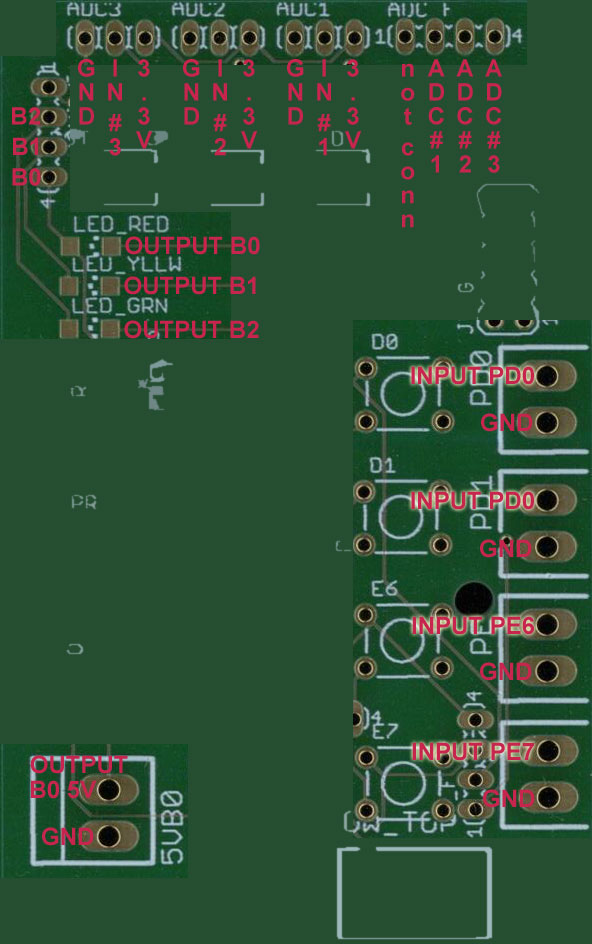
The addon shield is stacked on to the top of the brick board. The 5 male / female contacts need be be connected precisely to ensure proper operation.
Timing characteristics
Serial Ports
Serial Port 0 is the debug port. It is not important for normal operation. Serial Port 1 is used for communication with the Base station via the XBee radio module. Both ports have, besides the different baud rate, the following setup. Byte Size = 8; no parity and 1 Stop Bit.
| Version | V1 | V2 |
|---|---|---|
| Serial Port 0 Baud Rate | 9600 | 57600 |
| Serial Port 1 Baud Rate | 9600 | 9600 |
Direct Rule Engine
Note: This chapter applies to Version 2.0 only. Brick Version 2 is clocked with 8 MHz. The rule engine is partly driven by interrupt service routines. The execution time for a non interrupted service routine is approx. 320 ys (10^-6 s). The test setup is as follows:
The Direct Rule Engine is configured in the way, that a external interrupt via digital Input channel E7/INT7 triggers the digital outport B0. As soon as the signal on E7/INT7 changes from 1 to 0, the rule triggers, that outport B0 changes from high to low. The time difference between input and output is measured externally with an oscilloscope. Find below the screenshots of the measurement.
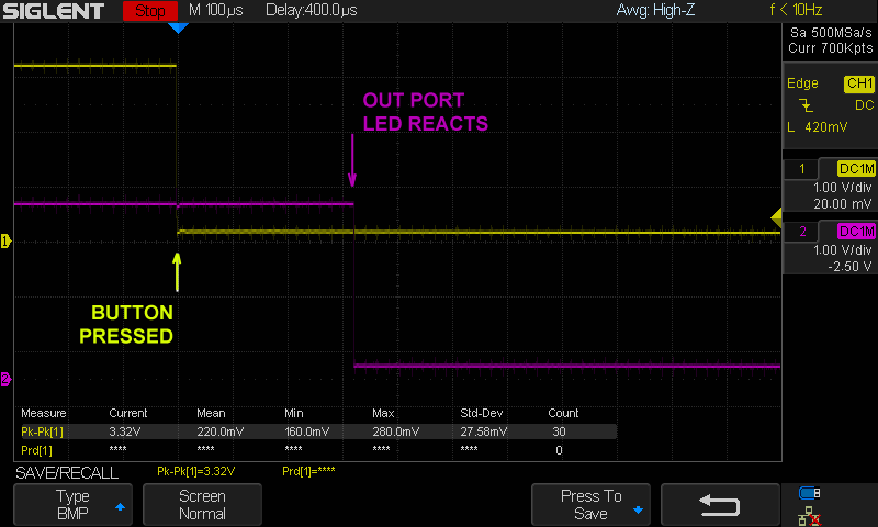
Here we zoomed in... to obtain a better resolution. Lets say 320 ys.
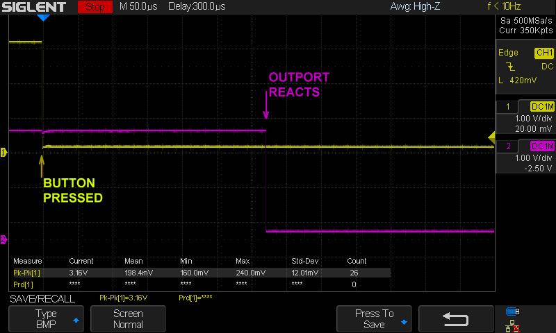
With the cpu frequency of 8 MHz and a delay time of 320 ys the processor needs 2560 cycles to process the external request. Assuming the program has a couple of jumps and sram readings we can assume that in average 2 clock cycles are used. This still executes 1280 lines of code before reaching an output.
Feature matrix
This matrix compares the capabilities of different brick versions helps you to decide whether to update or not.
| Module / Functionality | V1 | V2 |
|---|---|---|
| 1-wire support (# devices supported) | 1 | 1 |
| # Digital input ports | 4 | 4 |
| # Digital output ports | 4 | 3 |
| # Digital output power ports | 1 | |
| # Analog input ports | 3 | |
| Brick Direct Rule Engine | ||
| 3V battery power in | ||
| 5V micro USB power in |
Not supported
Fully supported